
Compliments of Firestik® Antenna Company, Arizona USA
(tel) 602-273-7152
Updated 2023.12.07
|
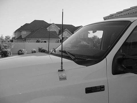
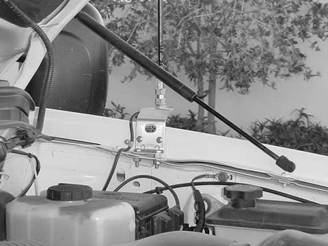
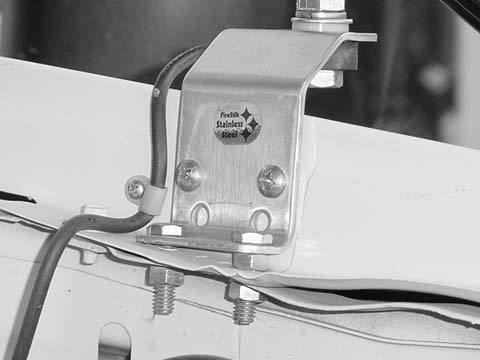
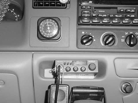
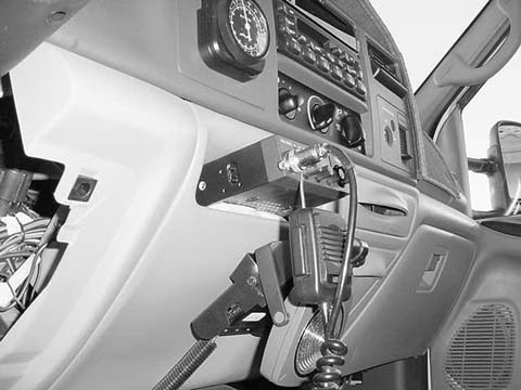
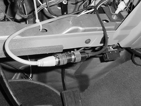
The MK-174 (Mini-Kit) has the SS-174 mount and K-8R18 coax in one kit. This is the best way to obtain the mount and coax. Aside from costing less than purchasing the individual components, you have all of the right parts for properly mounting the FireRing terminated coax to the mounting bracket. Read this completely before doing your installation. While there are numerous variations to every installation you might find some helpful information that will assist you in your installation. Also, some modifications were made to the bracket after this installation was made (mounting hole pattern). Nonetheless, installation remains the same. BRACKET INSTALLATION The bracket was mounted on the driver's side of the vehicle (see photo 1) in this installation for four reasons. (1) The AM/FM antenna would not interfere with the transmission pattern. (2) The vehicle was used for pulling a travel trailer that might block some of the signal on the highway side of the vehicle.(3) Less chance of the antenna being exposed to tree limbs overhanging the road. (4) Vehicle sometimes used off-road so driver always has visual contact with the antenna. The bracket was located between the windshield and the location on the inner fender edge where the hood support piston is mounted (see photo 2). There is a forward slope of the hood line on this vehicle so the installation was slightly modified in order to have the antenna perfectly vertical. To gain unobstructed access to the mounting location, the hood support piston was temporarily disconnected from the fender bracket. The hood will need support before the hood piston is disconnected as one piston will not support the weight (a sturdy stick will do). To remove the hood piston from the bracket, carefully remove either the top or bottom retainer ring from the piston and move it out of the way. The bracket was placed on the hood channel in a location that allowed access to the under side. The two lower bracket holes were marked on the bottom of the hood channel and 1/4-inch holes were drilled through. A 1/4-inch x 1-inch long bolt was placed through the front hole of the bracket and a nut was ran up the bolt until it met the bracket (see photo 3). This nut located under the front edge allowed the bracket to be adjusted so that the front to rear angle of the antenna was perfectly vertical. The mount was then placed on the fender edge and lightly secured with 1/4-inch bolts, lock washers and nuts. Note: Put the antenna on the bracket so you can better judge the front to rear angle). After the down bolts are lightly tightened, place two pilot holes (#20 drill or between 0.150" and 0.161") on the inside edge of the fender to secure the bracket. Use two of the #12 stainless steel sheet metal screws to fasten the bracket to the vertical edge of the inner fender surface. After the two sheet metal screws are tight, tighten the 1/4-inch down bolts. Once secured, there may be a slight left to right tilt on the antenna. If so, adjust a crescent wrench to the thickness of the bracket and "tweak" it as required to make the antenna vertical in that plane. COAX CABLE INSTALLATION The antenna stud and FireRing coax was secured so that the coax feed from the FireRing was facing the driver. The nylon cable clamp was used to secure the coax to the inner edge of the vertical fender surface at the rearward edge of the mounting bracket. A small stainless steel sheet metal screw is provided for the cable clamp. Routing the coax to the inside of the vehicle can often be the most trying part of the installation. If you can find a convenient place on the firewall to pass the end of the coax through, your job will be easier. On our trial installation we dropped the coax down through the engine compartment and drilled a 1/4-inch hole from under the vehicle a couple of inches towards the passenger side of the spot where the emergency brake cable enters the passenger compartment. There is no specific rules for getting the cable into the vehicle but you should take care not to have the coax resting against hot surfaces or moving parts such as the steering shaft. Also beware of sharp edges that could fray the outer protection of the coax. On our trial installation we used silicone sealer to protect and anchor the coax in the hole we made. You will have excess coax and it can be carefully tie-wrapped under the hood or under the dash. THE RADIO The user installed a Uniden Pro 520XL radio. It is small and has all the basic features you need in a radio plus RF gain control. The radio is small enough to go into the little cubbyhole (see photo 4 and photo 5) at the bottom of the dash, just to the right of the steering column (this will require the use on an external speaker because the built in radio speaker is confined to cubbyhole). Two holes were made in the back of the cubbyhole with a 1-inch hole saw that lined up with the power and coax feeds on the back of the radio. These holes allowed the power lead, external speaker wire, PA horn lead and antenna coax to be routed to the back of the CB. Power for the CB was taken straight from the battery to eliminate "dirty" [noise causing] power from under the dash. The radio was not hard mounted to the vehicle … the user just packed some foam rubber around it to hold it snug in the cubby hole. FORE THOUGHT To make antenna testing easier (the radio won't need to be removed from the cubbyhole to get to the antenna connection), a 3ft jumper (Firestik model R-36) was connected to the radio and routed to the under-dash access area (behind removable panel under steering column). To compensate for the added jumper, 3 feet was removed from the antenna coax lead before the PL-259 was installed (to keep the overall length at the preferred 18-foot measurement). The jumper and the primary lead were connected together (see photo 6) with a standard barrel connector (Firestik model AR-4). When SWR needed set/checked the radio did not need to be extracted from the cubbyhole. The access panel under the column was removed and the ends of the jumper and antenna lead were readily available for direct connection to the SWR meter. All that was required was to remove the barrel connector and to place the SWR meter in-line (some people leave their meter in-line at all times). ABOUT ANTENNAS The most popular antenna selected for this type of installation is the FS3, 3-foot Firestik II. If you want a lighter antenna you may use the FL3 3-foot FireFly. For added bandwidth, select either the FL4 or FS4 antenna. You can use an FS2 2-foot antenna but there will be limitations. The offset location limits available ground plane for the antenna and the inherent characteristic of short antennas limit bandwidth. We were unable to achieve sub-2.0:1 SWR across all 40 CB channels. However, the vehicle owner stated that he only used channels below 20 for day to day use and would prefer the convenience of a short antenna since the vehicle was in and out of his garage on a daily basis. Inasmuch as he only used half of the radio's bandwidth, we tuned the FS2 antenna for maximum performance at channel 10 (center of channels 1 thru 20) instead of channel 19. The user also had an FS4 antenna that he kept on-hand and used when he was on road trips and the extra height was not a daily issue. The FS4, having more bandwidth, was tuned across all 40 channels. Both antennas were tuned at the time of mount installation so the user could change from the FS2 to the FS4 (and back) without tuning at the time of exchange.
|
Compliments of Firestik® Antenna Company, Arizona USA
(tel) 602-273-7152
Updated 2023.12.07