IDENTIFYING FIRESTIK
NO-GROUND-PLANE ANTENNAS
Compliments of Firestik® Antenna Company Technical Support Team
Copyright © 1996 Firestik® Antenna Company
|
If you are using a Firestik antenna for CB communication, it is imperative for you to know whether your system is a standard ground plane (GP) set-up or a no-ground-plane (NGP) antenna system. There is a distinct difference. You may not, under any circumstances, interchange Firestik antennas or coax cable assemblies between the two types of systems. It will not work and doing so may damage your radio. Furthermore, you may not use a non-Firestik NGP antenna with a Firestik NGP coax assembly. Firestik NGP systems are unique. You can identify our NGP system in one of two ways. The coax assembly and the antenna itself. The Coax The NGP coax assembly is black with identifying print in silver-grey. Assemblies made before February 2004 are printed with "Fire-Flex" RG-58A/U. Those made after February 2004 are printed with Firestik Super-Shield 50. The connector at the radio end has a soldered tip (not crimped). Also, at the radio end you will find the coax is covered with a piece of black shrink tubing that is about 18 inches (46cm) long. At the mount end of the assembly the center conductor of the coax has been preprocessed and ready to have the ring terminal installed by the user. The braided shield of the coax is not used at the mount end. The Antenna All NGP antennas leave the factory with a yellow band around the antenna just above the base. The heavy-duty fiberglass antennas are referred to as the "FG" series and to the non-expert eye will appear similar to the standard " FS" (Firestik II) series antennas. The light-duty fiberglass models are referred to as the "LG" series and have a similar appearance to the "FL" (FireFly) series antennas. If the yellow band has been removed, measuring the length of the close wound section (loading coil) of the antenna will help you tell the difference between the NGP antenna and its near counterpart. The following table gives you the length of the close wound section of our antennas. First measure the over all length of the antenna to determine if it is in the 2, 3, 4 or 5 foot range. Next, measure the distance from the top of the antenna (not including the tunable tip mechanism) to the bottom edge of the close wound section of the antenna. Compare your measurements to the information in the chart below to properly identify the antenna. 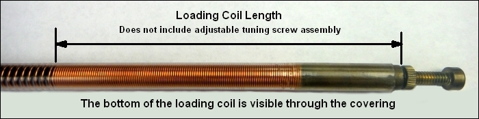
|

Updated 2023.12.07