Step by Step Text
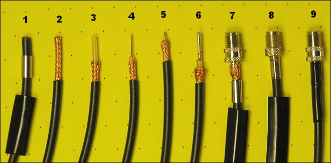
- Starting with flush cut RG-58 type coax, slide shrink tubing and crimp ring over coax.
- Remove 1 inch (25mm) of the black outer covering on the coax.
- Cut off 1/2 inch (12mm) of the copper braid.
- Remove 1/2 inch (12mm) of the center wire insulator.
- Remove 3/8 inch (9mm) of the center conductor wire
- Push braid away from end, heat center wire and tin (add small amount of solder) to the center conductor.
While still hot, use a pair of tweezers or needle nose pliers to install brass center pin to the coax center conductor. Apply a little heat to the pin so the solder adheres to it.
- Push connector body over brass pin then pull copper braid over the connector end sleeve.
- Slide crimp ring over braid and crimp.
- Slide the shrink tubing over crimp ring; apply heat (non-open flame source such as a heat gun, hair dryer or teapot steam).
It is a good idea to check out the installation with a test meter. Shorts or opens will cause tuning issues. A Standing Wave Ratios(SWR) that is excessively high (over 3.0:1) can cause damage to the radios transmit circuitry. So ...
- There should be continuity to center conductor connections, end to end.
- There should be continuity to shield connections, end to end.
- There should not be continuity from center conductor to shield.
If this installation coincides with the Mini-UHF to PL-259 adapter, screw (hand tight only) the PL adapter to the mini-UHF connector just installed in previous procedure.