ELECTRICALLY LONG NGP ANTENNA SYSTEMS
Compliments of Firestik® Antenna Company Technical Support Team
Copyright © 2007 Firestik® Antenna Company
|
This article will be of interest to, and was specifically written for those who have installed a Firestik no-ground-plane ( NGP) antenna system and are faced with an "electrically long" situation after having made the maximum antenna adjustment. Maximum adjustment means that the tuning screw is down as far as it can go, or in the case of wire whip style antennas, the whip has been lowered as far as it can go into the base coil. Unlike non-NGP systems, the length of the NGP coax cable figures into the overall electrical length of the entire system. Accordingly, manipulating the length of the coax can be used to alter the base frequency on electrically long systems. It cannot, however, be used to correct an electrically short NGP antenna system. Before going any further, understand that standing wave ratio (SWR) meters measure everything from the coaxial connector to the tip on the antenna. SWR readings will also reflect antenna environmental conditions, such as metallic objects that are near the antenna, especially if parallel to the antenna mast. When tuning, you are taking everything into account so you should tune the system just as it will exist in actual use. Do not rule out any component or condition. Also keep in mind that the NGP antennas and coax are not interchangeable with non-NGP antennas or coax assemblies. Due to the many conditions that can be encountered, insofar as installation location is concerned, Firestik errs on the safe side when establishing the manufacturing tolerances of the no-ground-plane (NGP) antennas and their matching coaxial cable assembly. In most cases, the antenna has sufficient tuning range to compensate for the variations in over 90% of the installations. Yet, there are exceptions. On some NGP installations the SWR will indicate an "electrically long" condition and the available tuning range of the mechanical antenna adjustment is insufficient to bring the resonant frequency of the system into an acceptable range. For this discussion, it is important that you do not confuse the terms "electrically long or short" and "physically long or short". A physically long or short antenna can very well be electrically short or electrically long when tested. Physical length is something you can measure with a ruler. Electrical length, for the purpose of this discussion, refers to the resonant frequency of the system. An SWR meter is used to determine the electrical length of the system. You cannot guess at what the SWR is on any system: not by how well somebody says you are sounding, not by how well you are hearing someone else. It MUST be measured with an SWR meter. Guessing is a dangerous proposition and will generally result in rendering the coax assembly useless and beyond repair. So, unless you understand the SWR process, you should think twice before you start messing with the coax cable. Proceed with knowledge and with caution. While you do not have to be a rocket-scientist to work the NGP antenna system, you need to understand basic "cause and effect" actions before you strap on your tool belt to go "to fixin' the dern thing". Firestik created and posted an SWR plotting chart that you can print on your printer and use while testing and tuning your antenna system. The chart is in PDF format and laid-out in the landscape orientation. To access the plotting chart for printing, click here - SWR Plotting Chart. To determine that an electrically long condition exists, the SWR on CH40 MUST be a higher value than the SWR on CH1. And again, for the purpose of this discussion, the maximum adjustment should have been made via the antenna. SWR on an electrically long installation will ALWAYS be higher on channel 40 than it will be on channel 1. A plotted SWR curve might look like the following graphic depiction. 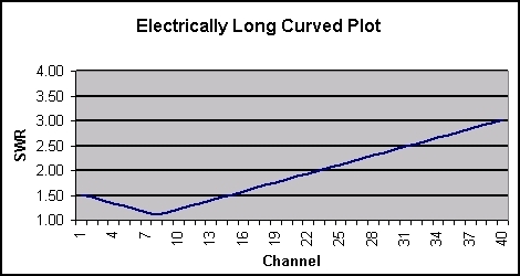 Keep in mind, for optimum performance across all 40 CB channels, the SWR on CH1 and CH40 will be identical, or very close, usually plus/minus 0.1. Depending upon the installation and the antenna system used, the SWR on your vehicle may vary from that shown on the following chart. Ideally, the CH1 & CH40 SWR will be 2.0:1 or lower across the channels being used. Transmitting on channels where the SWR exceeds 3.0:1 should be avoided to protect the circuits in the CB radio. The following graphic depicts a balanced, 40-channel SWR curve. 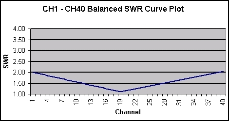
Coaxial Cable AdjustmentIf, and only if, your installation meets the "electrically long" criteria, Use the following procedure for adjusting the resonant frequency of the coaxial cable assembly.
Notes: 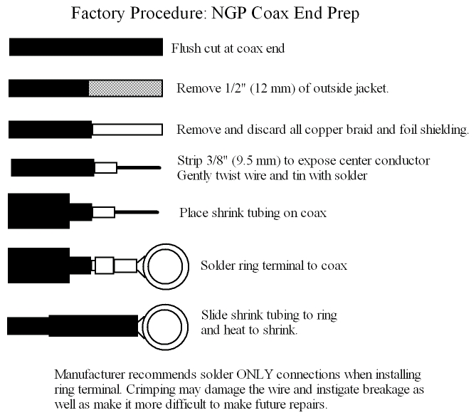 |

Updated 2023.12.07