Electrically Too Long Tunable Tip Antennas
Compliments of Firestik® Antenna Company Technical Support Team
Copyright © 2011 Firestik® Antenna Company
|
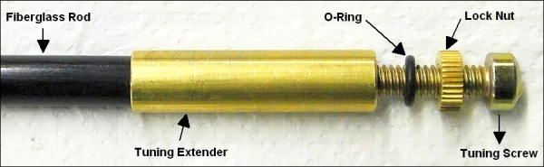
As rare as the case may be, every once in a while the SWR on a tunable-tip antenna will indicate an electrically long condition, even when the tunable tip is screwed down as far as it can go. Electrically long means that the SWR on CH40 is higher than it is on CH1. This may occur if too many accessories are installed between the mount and the antenna or when the counterpoise (ground-plane) that the antenna can utilize is well beyond the average (determined by decades of experience and in-field feedback). It is a bit of an upside-down world with antennas. You must seperate "physically longor short" (measured in inches, centimeters, etc.) from "electrically long or short" (measured in radio wave frequency, which in reality is a combined time and distance measurement ). In a way, both are related and unrelated to one another. Antennas that are electrically long require the frequency to be increased by removing wire, turning down a tuning screw or, reducing the physical length in the case of wire whip antennas or wire impregnated fiberglass antennas. The exact is opposite with electrically short antennas. To lengthen them, you need to decrease the frequency. For the most part, you don't need to wrap your brain around the physics ... just remember that if the antenna is electrically short, that is the SWR on CH1 is higher than it is on CH40 it needs to be adjusted in a way that makes it physically longer. The opposite for electrically long antennas with SWR readings showing CH40 to be higher than CH1. In the simplist term, electrically short antennas need more and electrically long antennas need less. Beyond the features of a tunable-tip antenna that can not be changed by the installer (amount of wire, the fixed tuning extender and the physical length of the antenna), there are user adjustable options with the add-on items (tuning screw, locking nut, o-ring and vinyl tip) that will have an effect on the electrical length of the antenna. None of those four items are mandatory . If the SWR is balanced between CH1 and CH40 with the tuning screw completely removed, the fact that one or all of the components are not on the antenna will have no effect on it performance. You do whatever the SWR readings dictate. When we test and record data on tunable tip antennas, we look at them from a minimum/maximum point of view. The electrically shortest condition occurs when the tuning screw, locking nut, o-ring and vinyl tip is removed. The longest condition occurs when the tuning screw is in the maximum out position, the locking nut and o-ring is present and the vinyl tip is installed. Therefore, everything between those two scenarios (the frequency/SWR range) is possible. What we cannot do is tell you exactly what and how much adjustment to make because almost every installation is different. How it is mounted, where it is mounted, and what vehicle accessories are present will effect tuning and performance. And because of that, we suggest the following procedure on antennas that test too long. First, remove the tuning screw, locking nut, o-ring and vinyl tip and check the SWR on CH1 and CH40. If the SWR is still higher on CH40, the only user available option has to do with the number and length of accessories (springs, quick disconnects, lift-n-lay joints) between the antenna and the mount. In normal situations, adding accessories on the bottom of the antenna can be offset with adjustments at the top of the antenna. But, your condition is abnormal and repositioning the antenna relative to available ground plane may be necessary. However, if the SWR is now higher on CH1 than CH40 (electrically short condition), you can start adding pieces and parts.
There is rarely a scenario that cannot be compensated for by manipulating the add-on parts. Probably the ideal manipulation would be a 50-60% reduction on the screw length, the locking nut installed and no more than 1/2-inch (25mm) of the vinyl tip cut off and finding yourself needing to adjust the tuning screw a couple of turn in either direction to achieve equal SWR on CH1 and CH40. As always, if you need reassurance of the process or have other concerns, you can always call and ask for technical assistance. How and what to do |

Updated: 2023.12.05