INTRO TO SWR
Compliments of Firestik® Antenna Company Technical Support Team
Copyright © 1996 Firestik® Antenna Company

|
General Information
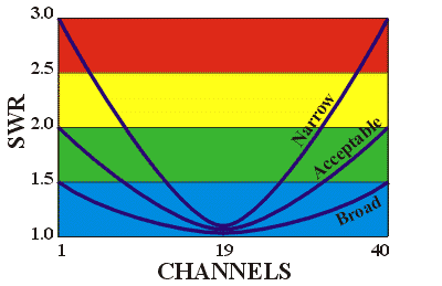
As in most matters involving the technical side of antennas, "SWR" can be complex beyond the understanding and concern of many radio communicators. In this discussion we will attempt to simplify the SWR subject. If you need or want more detailed information, there are plenty of good books that are loaded with antenna testing information. In the meantime, this information will help the newcomer understand the basic concept. "SWR" is the common abbreviation for "Standing Wave Ratio". It may, in some circles, be referred to as "VSWR (voltage standing wave ratio). Never the less ... it is the same. For the most part the term has been reduced to SWR since the calculation can involve either voltage or current. The voltage/current is measured in a transmission line scenario that involves a source (in this case, a radio capable of transmiting radio signals) and a load (everything from the coaxial connector at the radios output to the end of the antenna). In simple terms ... SWR compares the maximum amount of voltage or current that can be delivered by the radio to the minimum voltage or current that actually leaves via the transmission line and antenna. If everything, from the radio end connector to the base of the antenna is perfect, and if the antenna is perfectly tuned to the testing frequency, SWR will be 1:1. That is, every bit of power that the radio has to deliver is leaving the radio. For frequencies below 200 MHz (CB, VHF, etc), SWR below 2.0:1 is acceptable. Granted, lower SWR means more power leaving the radio but, at 2.0:1 the loss does not amount to more than 1/2 dB, even on very long transmission lines. A loss of 1/2 dB is an undetectable change in actual signal strength. Short of having an easy to tune antenna, fighting to achieve SWR in the 1.3:1 to 1.6:1 range when it is already at 2.0:1 probably isn't worth the time and effort. Many people believe that SWR only involves the antenna but that is an inaccurate assumption. When you place an SWR meter between the radio and the antenna it cannot decipher one component from another. A defective connector, bad coaxial cable, faulty or improperly installed stud mount or a defective and perhaps untuned antenna may all return the same results on the meter. Not only that, but how the antenna is mounted will also play a big part in the resulting SWR readings. For instance, on a ground-plane dependent mobile antenna, if the mount doesn't have a chassis ground the results could be higher than expected SWR. Just as well, if the antenna is mounted on the vehicle in a way that hampers its ability to radiate the applied energy into free space, you will experience less than optimum SWR. Antennas, for the purpose of this discussion, will only be resonant at one primary frequency. For example, on a 40 channel CB, channel 19 is the center frequency (27.185 MHz). If the antenna is tuned to be resonant on channel 19, the further away from that channel you are, the higher the SWR will be. On occasion you may hear someone say the "SWR should dip at the center frequency". With the antenna tuned at channel 19, if you were to plot the SWR from channel 1 to channel 40, the results would be curved line with both channel 1 and channel 40 being equal but higher than channel 19. The steepness of the line as it leaves the center frequency indicates the bandwidth of the antenna. The flatter the line, the broader the bandwidth. See the following chart for visual assistance. |
|
 Note: Even though this section focuses on CB frequencies, do note that the general concept applies to all transmitters and their associated antennas. What applies here also applies to other frequenciews as well. To accomplish the lowest SWR on channel 19 (center frequency dip) you need to check SWR on channels 1 and 40. The SWR difference between these two channels will tell you if the antenna is electrically short (channel 19 resonant frequency too high) or electrically long (channel 19 resonant frequency too low). With that in mind, the SWR meter is placed in-line between the radio and the coaxial cable that feeds the antenna. The next step involves meter calibration. In this case, calibration involves measuring the radios maximum output potential. Depending upon the meter design, the switch on the meter will be in the Reference (REF) or Forward (FWD) position (in this position the radios maximum power is established). With the radio set to channel 1, the microphone button is depressed and the calibration knob on the meter is turned until the meter needle aligns itself with the calibration line on the meter face. This is establishing a reference point for the radios maximum output at channel 1, whatever it may be. Once calibrated, the meter switch is changed to the Reverse (REV) or SWR position and the SWR reading is noted and recorded. Now change the radio to channel 40, place the meter into the FWD or REF position and recalibrate for channel 40 by depressing the microphone button and turning the meter adjustment knob. Once calibrated, switch meter to the REV or SWR position and record the SWR reading. NOTE: If at anytime during the SWR measurement process the meter needle jumps to the extreme right edge of the scale (pegging the needle), do not operate the radio. You most likely have a short in the coaxial cable, connections or the antenna stud mount that must be repaired prior to any further action. With the SWR readings on channels 1 and 40 you can determine the tuning needs of the antenna. For assistance, see the related article on our web site ... "Setting the SWR of your Antenna" |

Updated: 2023.12.05